Use Raspberry Pi Pico, DHT11, SSD1306 OLED to make thermo-hygrometer
Recently, I want to use Raspberry Pi Pico, DHT11 THS and SSD1306 OLED screen to make a thermo-hygrometer. Although the official sample has these two devices, but I encountered a big pit, so I wrote this article to record the whole process. I want this project as a beginning of learning microcontroller.
This article will implement a program that can display the current temperature and humidity on the SSD1306 OLED screen, and also output this information through USB.
I put the source code in GitHub-ZhongUncle/pico-temp-hum-oled, and compiled it in the build directory for readers to try. But the comment of it is in Chinese, if you want to read English, please read comment in this blog.
Development tools and environment
Install pico-sdk and configure related environment variables. For this part, please refer to my other blog “How to use the Mac terminal to build C/C++ programs for Raspberry Pi pico for development, and how to deal with various problems without using any IDE or editor (such as VS Code )》, I won’t repeat here.
Prepare materials
The materials required:
- Raspberry Pi Pico or Pico W;
- SSD1306 OLED screen;
- DHT11 temperature and humidity sensor;
- Several wires;
- Breadboard;
- Breadboard power supply (optional, as the Pico will suffice for powering the sensors and screen).
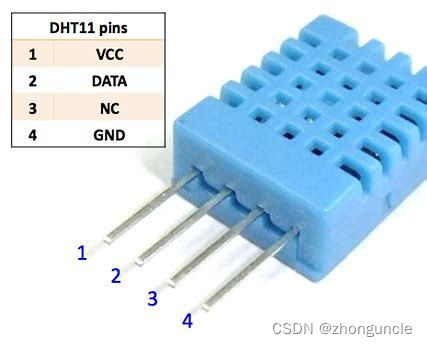
DHT11 has two types: 3-pin and 4-pin:
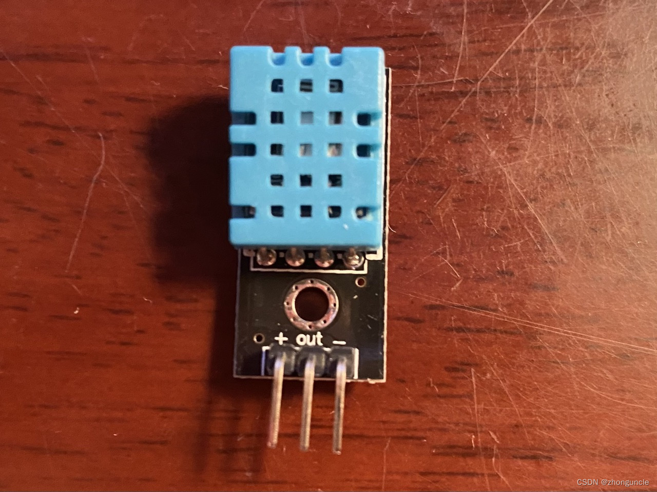
If it is 4-pin, not use pin 3:
If you have read the official documents or some other tutorials, you may see that we need a resistor (10k or 4.7k ohms) to pull up the data line, but this resistor does not actually affect the official code from running. In fact, It is not needed for operation, so it doesn’t matter.
Connect
The pin diagram of Pico is as follows:
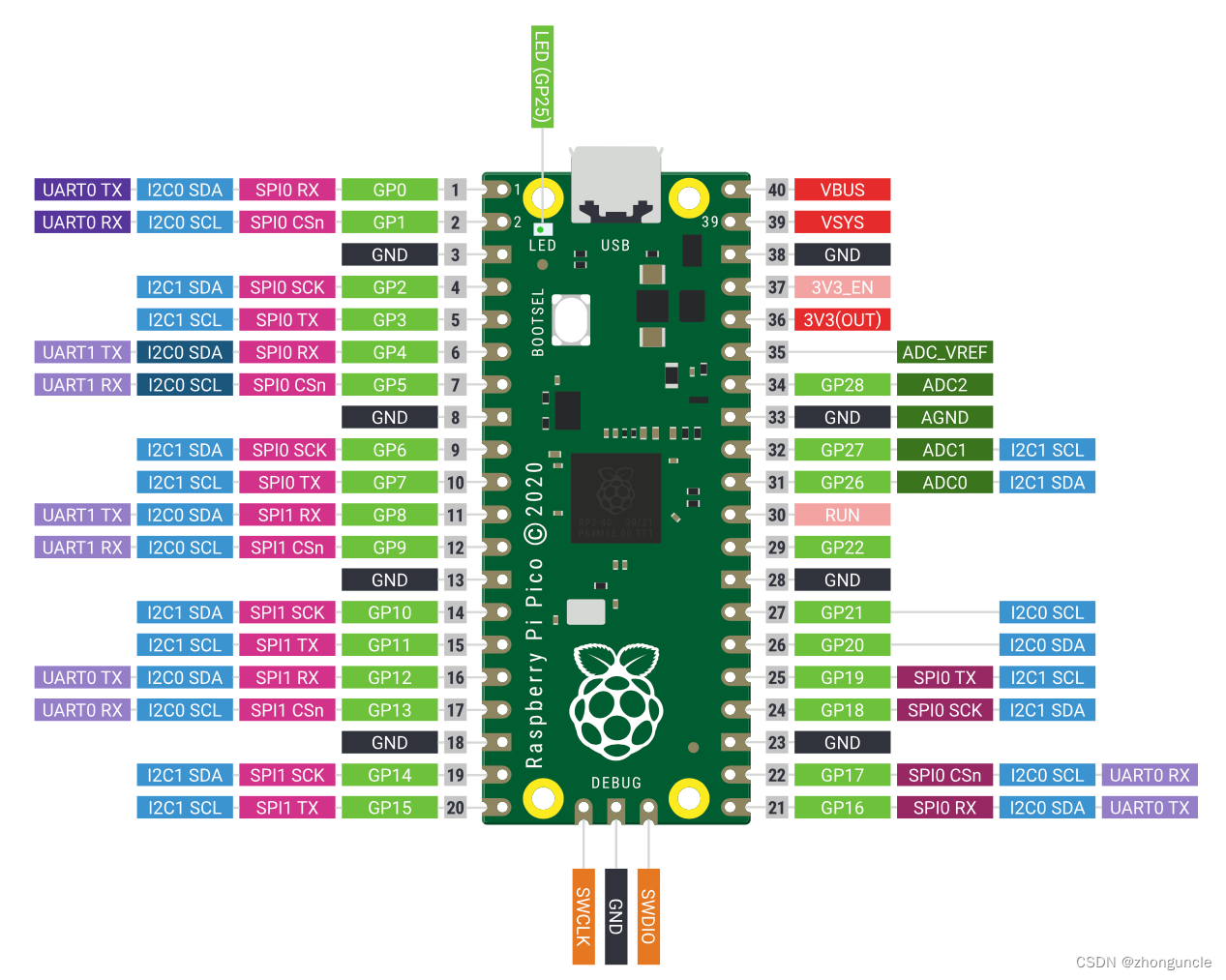
The power supply for the entire circuit from Pico, using Pin 38 as ground and Pin 36 as the power. 3.3V meets both sensors. Generally, the sensor is marked with power and ground pin, so be connected according to the marks.
The SCL pin of the SSD1306 is connected to Pin 7 of Pico, while the SDA pin is connected to Pin 6 of Pico. These two pins were chosen because they are Pico’s default I2C protocol interface, and the SSD 1306 communicates according to the I2C protocol. You can also modify the pins, but this article uses the default pins.
If you want to use other pins, you can see below blogs:
- This blog is for any situation: “Choose I2C controller, SDA and SCL pins using C/C++ on Raspberry Pi Pico”
- This blog is for only one I2C device: “Modify the default SDA and SCL pins of I2C using C/C++”
If you don’t know what is I2C, here is an introduction:BASICS OF THE I2C COMMUNICATION PROTOCOL
The data pin of DHT11 can be connected to any GP pin of Pico. GP15 or GP16 is recommended, because these two are usually close to the sensor on the breadboard and require shorter wires.
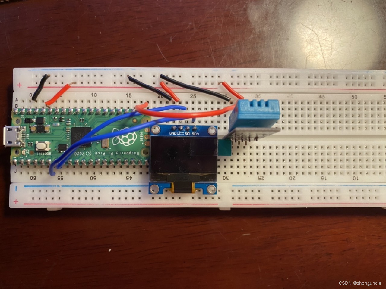
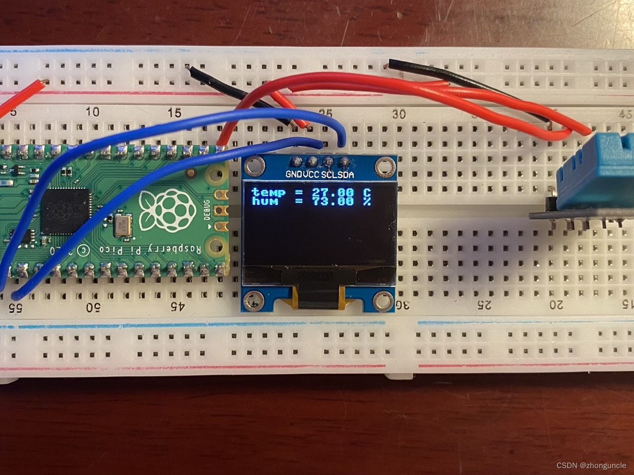
The image of linked devices is:
Structure of Project
Here is structure of project, you can see in GitHub-ZhongUncle/pico-temp-hum-oled.
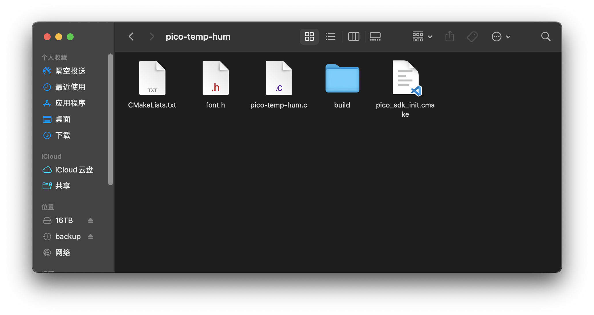
Create a new folder pico-temp-hum as root. Then go into it, create 3 files font.h, pico-temp-hum.c, CMakeLists.txt and a blank directory build. Finally, copy the pico_sdk_import.cmake file from pico-sdk to here:
$ mkdir pico-temp-hum
$ cd pico-temp-hum
$ touch font.h pico-temp-hum.c CMakeLists.txt
$ mkdir build
$ cp ../pico-sdk/pico_sdk_init.cmake pico_sdk_init.cmake
Now the structure of project looks like:
We can write code now.
Source code
font.h
First is font.h file, it stores font information.
There are two versions of SSD1306: 128x32 and 128x64. The pixels are divided into multiple pages by 8 rows vertically. For example, the 128x64 version in the picture above is arranged in RAM as follows:
       | COL0 | COL1 | COL2 | COL3 |  ...  | COL126 | COL127 |
PAGE 0 |      |      |      |      |       |        |        |
PAGE 1 |      |      |      |      |       |        |        |
PAGE 2 |      |      |      |      |       |        |        |
PAGE 3 |      |      |      |      |       |        |        |
PAGE 4 |      |      |      |      |       |        |        |
PAGE 5 |      |      |      |      |       |        |        |
PAGE 6 |      |      |      |      |       |        |        |
PAGE 7 |      |      |      |      |       |        |        |
--------------------------------------------------------------
In each page (determine pixels by row and column):
      | COL0 | COL1 | COL2 | COL3 |  ...  | COL126 | COL127 |
COM 0 |      |      |      |      |       |        |        |
COM 1 |      |      |      |      |       |        |        |
:     |      |      |      |      |       |        |        |
COM 7 |      |      |      |      |       |        |        |
-------------------------------------------------------------
So it is better to use 8 pixels as height of font. Here we use the font of the MicroPython project, which is 8x8 pixels format, its width and height are perfect for SSD1306 since 128 is exactly a multiple of 8.
Enter the following content in font.h (this font is not made by myself, so don’t delete the comments):
/*
 * This file is part of the MicroPython project, http://micropython.org/
 *
 * The MIT License (MIT)
 *
 * Copyright (c) 2013, 2014 Damien P. George
 *
 * Permission is hereby granted, free of charge, to any person obtaining a copy
 * of this software and associated documentation files (the "Software"), to deal
 * in the Software without restriction, including without limitation the rights
 * to use, copy, modify, merge, publish, distribute, sublicense, and/or sell
 * copies of the Software, and to permit persons to whom the Software is
 * furnished to do so, subject to the following conditions:
 *
 * The above copyright notice and this permission notice shall be included in
 * all copies or substantial portions of the Software.
 *
 * THE SOFTWARE IS PROVIDED "AS IS", WITHOUT WARRANTY OF ANY KIND, EXPRESS OR
 * IMPLIED, INCLUDING BUT NOT LIMITED TO THE WARRANTIES OF MERCHANTABILITY,
 * FITNESS FOR A PARTICULAR PURPOSE AND NONINFRINGEMENT. IN NO EVENT SHALL THE
 * AUTHORS OR COPYRIGHT HOLDERS BE LIABLE FOR ANY CLAIM, DAMAGES OR OTHER
 * LIABILITY, WHETHER IN AN ACTION OF CONTRACT, TORT OR OTHERWISE, ARISING FROM,
 * OUT OF OR IN CONNECTION WITH THE SOFTWARE OR THE USE OR OTHER DEALINGS IN
 * THE SOFTWARE.
 */
#ifndef MICROPY_INCLUDED_STM32_FONT_PETME128_8X8_H
#define MICROPY_INCLUDED_STM32_FONT_PETME128_8X8_H

static const uint8_t font[] = {
    0x00, 0x00, 0x00, 0x00, 0x00, 0x00, 0x00, 0x00, // 32=
    0x00, 0x00, 0x00, 0x4f, 0x4f, 0x00, 0x00, 0x00, // 33=!
    0x00, 0x07, 0x07, 0x00, 0x00, 0x07, 0x07, 0x00, // 34="
    0x14, 0x7f, 0x7f, 0x14, 0x14, 0x7f, 0x7f, 0x14, // 35=#
    0x00, 0x24, 0x2e, 0x6b, 0x6b, 0x3a, 0x12, 0x00, // 36=$
    0x00, 0x63, 0x33, 0x18, 0x0c, 0x66, 0x63, 0x00, // 37=%
    0x00, 0x32, 0x7f, 0x4d, 0x4d, 0x77, 0x72, 0x50, // 38=&
    0x00, 0x00, 0x00, 0x04, 0x06, 0x03, 0x01, 0x00, // 39='
    0x00, 0x00, 0x1c, 0x3e, 0x63, 0x41, 0x00, 0x00, // 40=(
    0x00, 0x00, 0x41, 0x63, 0x3e, 0x1c, 0x00, 0x00, // 41=)
    0x08, 0x2a, 0x3e, 0x1c, 0x1c, 0x3e, 0x2a, 0x08, // 42=*
    0x00, 0x08, 0x08, 0x3e, 0x3e, 0x08, 0x08, 0x00, // 43=+
    0x00, 0x00, 0x80, 0xe0, 0x60, 0x00, 0x00, 0x00, // 44=,
    0x00, 0x08, 0x08, 0x08, 0x08, 0x08, 0x08, 0x00, // 45=-
    0x00, 0x00, 0x00, 0x60, 0x60, 0x00, 0x00, 0x00, // 46=.
    0x00, 0x40, 0x60, 0x30, 0x18, 0x0c, 0x06, 0x02, // 47=/
    0x00, 0x3e, 0x7f, 0x49, 0x45, 0x7f, 0x3e, 0x00, // 48=0
    0x00, 0x40, 0x44, 0x7f, 0x7f, 0x40, 0x40, 0x00, // 49=1
    0x00, 0x62, 0x73, 0x51, 0x49, 0x4f, 0x46, 0x00, // 50=2
    0x00, 0x22, 0x63, 0x49, 0x49, 0x7f, 0x36, 0x00, // 51=3
    0x00, 0x18, 0x18, 0x14, 0x16, 0x7f, 0x7f, 0x10, // 52=4
    0x00, 0x27, 0x67, 0x45, 0x45, 0x7d, 0x39, 0x00, // 53=5
    0x00, 0x3e, 0x7f, 0x49, 0x49, 0x7b, 0x32, 0x00, // 54=6
    0x00, 0x03, 0x03, 0x79, 0x7d, 0x07, 0x03, 0x00, // 55=7
    0x00, 0x36, 0x7f, 0x49, 0x49, 0x7f, 0x36, 0x00, // 56=8
    0x00, 0x26, 0x6f, 0x49, 0x49, 0x7f, 0x3e, 0x00, // 57=9
    0x00, 0x00, 0x00, 0x24, 0x24, 0x00, 0x00, 0x00, // 58=:
    0x00, 0x00, 0x80, 0xe4, 0x64, 0x00, 0x00, 0x00, // 59=;
    0x00, 0x08, 0x1c, 0x36, 0x63, 0x41, 0x41, 0x00, // 60=<
    0x00, 0x14, 0x14, 0x14, 0x14, 0x14, 0x14, 0x00, // 61==
    0x00, 0x41, 0x41, 0x63, 0x36, 0x1c, 0x08, 0x00, // 62=>
    0x00, 0x02, 0x03, 0x51, 0x59, 0x0f, 0x06, 0x00, // 63=?
    0x00, 0x3e, 0x7f, 0x41, 0x4d, 0x4f, 0x2e, 0x00, // 64=@
    0x00, 0x7c, 0x7e, 0x0b, 0x0b, 0x7e, 0x7c, 0x00, // 65=A
    0x00, 0x7f, 0x7f, 0x49, 0x49, 0x7f, 0x36, 0x00, // 66=B
    0x00, 0x3e, 0x7f, 0x41, 0x41, 0x63, 0x22, 0x00, // 67=C
    0x00, 0x7f, 0x7f, 0x41, 0x63, 0x3e, 0x1c, 0x00, // 68=D
    0x00, 0x7f, 0x7f, 0x49, 0x49, 0x41, 0x41, 0x00, // 69=E
    0x00, 0x7f, 0x7f, 0x09, 0x09, 0x01, 0x01, 0x00, // 70=F
    0x00, 0x3e, 0x7f, 0x41, 0x49, 0x7b, 0x3a, 0x00, // 71=G
    0x00, 0x7f, 0x7f, 0x08, 0x08, 0x7f, 0x7f, 0x00, // 72=H
    0x00, 0x00, 0x41, 0x7f, 0x7f, 0x41, 0x00, 0x00, // 73=I
    0x00, 0x20, 0x60, 0x41, 0x7f, 0x3f, 0x01, 0x00, // 74=J
    0x00, 0x7f, 0x7f, 0x1c, 0x36, 0x63, 0x41, 0x00, // 75=K
    0x00, 0x7f, 0x7f, 0x40, 0x40, 0x40, 0x40, 0x00, // 76=L
    0x00, 0x7f, 0x7f, 0x06, 0x0c, 0x06, 0x7f, 0x7f, // 77=M
    0x00, 0x7f, 0x7f, 0x0e, 0x1c, 0x7f, 0x7f, 0x00, // 78=N
    0x00, 0x3e, 0x7f, 0x41, 0x41, 0x7f, 0x3e, 0x00, // 79=O
    0x00, 0x7f, 0x7f, 0x09, 0x09, 0x0f, 0x06, 0x00, // 80=P
    0x00, 0x1e, 0x3f, 0x21, 0x61, 0x7f, 0x5e, 0x00, // 81=Q
    0x00, 0x7f, 0x7f, 0x19, 0x39, 0x6f, 0x46, 0x00, // 82=R
    0x00, 0x26, 0x6f, 0x49, 0x49, 0x7b, 0x32, 0x00, // 83=S
    0x00, 0x01, 0x01, 0x7f, 0x7f, 0x01, 0x01, 0x00, // 84=T
    0x00, 0x3f, 0x7f, 0x40, 0x40, 0x7f, 0x3f, 0x00, // 85=U
    0x00, 0x1f, 0x3f, 0x60, 0x60, 0x3f, 0x1f, 0x00, // 86=V
    0x00, 0x7f, 0x7f, 0x30, 0x18, 0x30, 0x7f, 0x7f, // 87=W
    0x00, 0x63, 0x77, 0x1c, 0x1c, 0x77, 0x63, 0x00, // 88=X
    0x00, 0x07, 0x0f, 0x78, 0x78, 0x0f, 0x07, 0x00, // 89=Y
    0x00, 0x61, 0x71, 0x59, 0x4d, 0x47, 0x43, 0x00, // 90=Z
    0x00, 0x00, 0x7f, 0x7f, 0x41, 0x41, 0x00, 0x00, // 91=[
    0x00, 0x02, 0x06, 0x0c, 0x18, 0x30, 0x60, 0x40, // 92='\'
    0x00, 0x00, 0x41, 0x41, 0x7f, 0x7f, 0x00, 0x00, // 93=]
    0x00, 0x08, 0x0c, 0x06, 0x06, 0x0c, 0x08, 0x00, // 94=^
    0xc0, 0xc0, 0xc0, 0xc0, 0xc0, 0xc0, 0xc0, 0xc0, // 95=_
    0x00, 0x00, 0x01, 0x03, 0x06, 0x04, 0x00, 0x00, // 96=`
    0x00, 0x20, 0x74, 0x54, 0x54, 0x7c, 0x78, 0x00, // 97=a
    0x00, 0x7f, 0x7f, 0x44, 0x44, 0x7c, 0x38, 0x00, // 98=b
    0x00, 0x38, 0x7c, 0x44, 0x44, 0x6c, 0x28, 0x00, // 99=c
    0x00, 0x38, 0x7c, 0x44, 0x44, 0x7f, 0x7f, 0x00, // 100=d
    0x00, 0x38, 0x7c, 0x54, 0x54, 0x5c, 0x58, 0x00, // 101=e
    0x00, 0x08, 0x7e, 0x7f, 0x09, 0x03, 0x02, 0x00, // 102=f
    0x00, 0x98, 0xbc, 0xa4, 0xa4, 0xfc, 0x7c, 0x00, // 103=g
    0x00, 0x7f, 0x7f, 0x04, 0x04, 0x7c, 0x78, 0x00, // 104=h
    0x00, 0x00, 0x00, 0x7d, 0x7d, 0x00, 0x00, 0x00, // 105=i
    0x00, 0x40, 0xc0, 0x80, 0x80, 0xfd, 0x7d, 0x00, // 106=j
    0x00, 0x7f, 0x7f, 0x30, 0x38, 0x6c, 0x44, 0x00, // 107=k
    0x00, 0x00, 0x41, 0x7f, 0x7f, 0x40, 0x00, 0x00, // 108=l
    0x00, 0x7c, 0x7c, 0x18, 0x30, 0x18, 0x7c, 0x7c, // 109=m
    0x00, 0x7c, 0x7c, 0x04, 0x04, 0x7c, 0x78, 0x00, // 110=n
    0x00, 0x38, 0x7c, 0x44, 0x44, 0x7c, 0x38, 0x00, // 111=o
    0x00, 0xfc, 0xfc, 0x24, 0x24, 0x3c, 0x18, 0x00, // 112=p
    0x00, 0x18, 0x3c, 0x24, 0x24, 0xfc, 0xfc, 0x00, // 113=q
    0x00, 0x7c, 0x7c, 0x04, 0x04, 0x0c, 0x08, 0x00, // 114=r
    0x00, 0x48, 0x5c, 0x54, 0x54, 0x74, 0x20, 0x00, // 115=s
    0x04, 0x04, 0x3f, 0x7f, 0x44, 0x64, 0x20, 0x00, // 116=t
    0x00, 0x3c, 0x7c, 0x40, 0x40, 0x7c, 0x3c, 0x00, // 117=u
    0x00, 0x1c, 0x3c, 0x60, 0x60, 0x3c, 0x1c, 0x00, // 118=v
    0x00, 0x1c, 0x7c, 0x30, 0x18, 0x30, 0x7c, 0x1c, // 119=w
    0x00, 0x44, 0x6c, 0x38, 0x38, 0x6c, 0x44, 0x00, // 120=x
    0x00, 0x9c, 0xbc, 0xa0, 0xa0, 0xfc, 0x7c, 0x00, // 121=y
    0x00, 0x44, 0x64, 0x74, 0x5c, 0x4c, 0x44, 0x00, // 122=z
    0x00, 0x08, 0x08, 0x3e, 0x77, 0x41, 0x41, 0x00, // 123={
    0x00, 0x00, 0x00, 0xff, 0xff, 0x00, 0x00, 0x00, // 124=|
    0x00, 0x41, 0x41, 0x77, 0x3e, 0x08, 0x08, 0x00, // 125=}
    0x00, 0x02, 0x03, 0x01, 0x03, 0x02, 0x03, 0x01, // 126=~
    0xaa, 0x55, 0xaa, 0x55, 0xaa, 0x55, 0xaa, 0x55, // 127
};

#endif // MICROPY_INCLUDED_STM32_FONT_PETME128_8X8_H
I am creating fonts based on the system fonts of Mac OS 3.2. This font is very beautiful and is also a bitmap font. I implemented some letters and found that they are indeed much more beatiful, but the implementation is not easy. Because the width and height of this font are not 8 or a multiple of 8, some adjustments are needed. If it is done, the content above and in the GitHub project will be replaced.
pico-temp-hum.c
Header
First add header:
#include <stdio.h>
#include <string.h>
#include <stdlib.h>
#include <ctype.h>
#include <math.h>
#include "pico/stdlib.h"
#include "hardware/i2c.h"
#include "hardware/gpio.h"
#include "ssd1306_font.h"
Code for SSD1306
Add some macros that may be used later, most are SSD1306 commands. Please see comment for usage:
// Set SSD1306_HEIGHT to 32 or 64 according to your SSD1306
#define SSD1306_HEIGHT              64
#define SSD1306_WIDTH               128

#define SSD1306_I2C_ADDR            _u(0x3C)

// The SSD1306 clock frequency. It is generally 400000 (40MHz), but there will be flickering. In order to slow down the flickering and improve the response speed,recommend to use 1000000 (100MHz).
#define SSD1306_I2C_CLK             1000000

// Commands of SSD1306 (see more in https://www.digikey.com/htmldatasheets/production/2047793/0/0/1/ssd1306.html)
#define SSD1306_SET_MEM_MODE        _u(0x20)
#define SSD1306_SET_COL_ADDR        _u(0x21)
#define SSD1306_SET_PAGE_ADDR       _u(0x22)
#define SSD1306_SET_HORIZ_SCROLL    _u(0x26)
#define SSD1306_SET_SCROLL          _u(0x2E)

#define SSD1306_SET_DISP_START_LINE _u(0x40)

#define SSD1306_SET_CONTRAST        _u(0x81)
#define SSD1306_SET_CHARGE_PUMP     _u(0x8D)

#define SSD1306_SET_SEG_REMAP       _u(0xA0)
#define SSD1306_SET_ENTIRE_ON       _u(0xA4)
#define SSD1306_SET_ALL_ON          _u(0xA5)
#define SSD1306_SET_NORM_DISP       _u(0xA6)
#define SSD1306_SET_INV_DISP        _u(0xA7)
#define SSD1306_SET_MUX_RATIO       _u(0xA8)
#define SSD1306_SET_DISP            _u(0xAE)
#define SSD1306_SET_COM_OUT_DIR     _u(0xC0)
#define SSD1306_SET_COM_OUT_DIR_FLIP _u(0xC0)

#define SSD1306_SET_DISP_OFFSET     _u(0xD3)
#define SSD1306_SET_DISP_CLK_DIV    _u(0xD5)
#define SSD1306_SET_PRECHARGE       _u(0xD9)
#define SSD1306_SET_COM_PIN_CFG     _u(0xDA)
#define SSD1306_SET_VCOM_DESEL      _u(0xDB)

// Height of page
#define SSD1306_PAGE_HEIGHT         _u(8)
// Number of pages
#define SSD1306_NUM_PAGES           (SSD1306_HEIGHT / SSD1306_PAGE_HEIGHT)
// Buffer of page content, this section will render to display in screen
#define SSD1306_BUF_LEN             (SSD1306_NUM_PAGES * SSD1306_WIDTH)

#define SSD1306_WRITE_MODE         _u(0xFE)
#define SSD1306_READ_MODE          _u(0xFF)
Create a structure to store data of rendering area, including the starting column and starting page, so that we can render the entire screen or only a part:
struct render_area {
    uint8_t start_col;
    uint8_t end_col;
    uint8_t start_page;
    uint8_t end_page;

    int buflen;
};
Declare a function to calculate the length of the rendering area and assign the value to the buflen variable of render_area. Because we may need to clear the buffer of the rendering screen, we need to know the length of the rendering area, otherwise some content will not be cleaned or overwritten. The specific situation will be mentioned later.
void calc_render_area_buflen(struct render_area *area) {
    // Calculate the length of rendering area
    area->buflen = (area->end_col - area->start_col + 1) * (area->end_page - area->start_page + 1);
}
Next is the code related to SSD1306 commands. SSD1306 supports a series of commands to operate the screen. Please check the datasheet for command details:
void SSD1306_send_cmd(uint8_t cmd) {
    // I2C write process expects a control byte followed by data
    // this "data" can be a command or data to follow up a command
    // Co = 1, D/C = 0 => the driver expects a command
    uint8_t buf[2] = {0x80, cmd};
    //First parameter indicates which i2c controller is used, i2c0 or i2c1. The default here is i2c0
    //Second parameter is the 7-bit address of the device to be read. This was set when defining the macro earlier and is 0x3C.
    //Third parameter is a pointer to the buffer to receive data. You may wonder, isn't the above an array? Array names in C are actually pointers)
    //Fourth parameter is the length of the received data (in bytes). Here it is 2
    //If the fifth parameter is true, then the host maintains control of the bus after exchanging data. Here is false
    i2c_write_blocking(i2c_default, SSD1306_I2C_ADDR, buf, 2, false);
}

void SSD1306_send_cmd_list(uint8_t *buf, int num) {
    for (int i=0;i<num;i++)
        SSD1306_send_cmd(buf[i]);
}

void SSD1306_send_buf(uint8_t buf[], int buflen) {
    //In horizontal address mode, the column address pointer is automatically incremented and includes the next page, so a buffer containing the entire frame can be sent in one exchange
    //Copy the framebuffer to a new buffer to add a control byte at the beginning
    uint8_t *temp_buf = malloc(buflen + 1);

    temp_buf[0] = 0x40;
    memcpy(temp_buf+1, buf, buflen);

    i2c_write_blocking(i2c_default, SSD1306_I2C_ADDR, temp_buf, buflen + 1, false);

    free(temp_buf);
}
Declare the initialization function of SSD1306. Notice the commands in cmds[] are all defined in the above macro area. Some need values as parameters, but some commands determine the setting values by themselves. This is just a simple array, not a special data structure.
void SSD1306_init() {
    /* Here is the default complete process for resetting the process, but different manufacturers may be different */
    uint8_t cmds[] = {
        SSD1306_SET_DISP,               // Close SSD1306
        /* Map memory */
        SSD1306_SET_MEM_MODE,           // Set address mode. 0 is the horizontal address mode, 1 is the vertical address mode, and 2 is the page address mode.
        0x00,                           // Set as horizontal address mode
        /* Resolution and Layout */
        SSD1306_SET_DISP_START_LINE,    // Set the start line to 0 (if no parameters, it is 0 by default)
        SSD1306_SET_SEG_REMAP | 0x01,   // Remap the partition, column address 127 is mapped to SEG0
        SSD1306_SET_MUX_RATIO,          // Set multiplex transmission rate
        SSD1306_HEIGHT - 1,             // Height of display minus 1 (because start from 0)
        SSD1306_SET_COM_OUT_DIR | 0x08, // Output scan direction. Here we scan from the bottom up, COM[N-1] to COM0
        SSD1306_SET_DISP_OFFSET,        // Set offset of display
        0x00,                           // We set no offset
        SSD1306_SET_COM_PIN_CFG,        // Set the COM (common) pin configuration. Pico will assign a special value

/* 128x32 resolution will use 0x02, 128x64 resolution can use 0x12. if it does not work, use 0x22 or 0x32 */
#if ((SSD1306_WIDTH == 128) && (SSD1306_HEIGHT == 32))
        0x02,
#elif ((SSD1306_WIDTH == 128) && (SSD1306_HEIGHT == 64))
        0x12,
#else
        0x02,
#endif

        /* Time and Drive schedule */
        SSD1306_SET_DISP_CLK_DIV,       // Set the displayed clock divide ratio
        0x80,                           // Divide ratio of 1 in standard frequency
        SSD1306_SET_PRECHARGE,          // Cycle of every exchange
        0xF1,                           // Vcc generate by Pico
        SSD1306_SET_VCOM_DESEL,         // Set VCOMH cancel level
        0x30,                           //0.83xVcc
        /* Display */
        SSD1306_SET_CONTRAST,           // Set contrast
        0xFF,							// Set contrast as 0xFF
        SSD1306_SET_ENTIRE_ON,          // Set the entire screen to display the contents of the RAM
        SSD1306_SET_NORM_DISP,          // Set up normal display (not upside down)
        SSD1306_SET_CHARGE_PUMP,        // Set charge pump
        0x14,                           // Vcc generate by Pico
        SSD1306_SET_SCROLL | 0x00,      // Set this will disables horizontal scrolling. This is important because if it is enabled, an error will occur when writing to memory
        SSD1306_SET_DISP | 0x01,        //Open SSD1306 display
    };

    SSD1306_send_cmd_list(cmds, count_of(cmds));
}
Function for rendering
Write the rendering function, it will render the data in the buffer to SSD1306:
void render(uint8_t *buf, struct render_area *area) {
    // use *area to update some area of SSD1306 display
    uint8_t cmds[] = {
        SSD1306_SET_COL_ADDR,
        area->start_col,
        area->end_col,
        SSD1306_SET_PAGE_ADDR,
        area->start_page,
        area->end_page
    };

    SSD1306_send_cmd_list(cmds, count_of(cmds));
    SSD1306_send_buf(buf, area->buflen);
}
The next step is to process characters. Program will find the characters required from character set in font.h, then convert and transfer them. Finally display them on the OLED:
/* Get the index of character 'ch' from character set */
static inline int GetFontIndex(uint8_t ch) {
    if (ch >= ' ' && ch <= 127) {
        return  ch - ' ';
    }
    else return  0; // If no index is found, return index of space
}

/* Output a character 'ch' to 'buf', start in (x, y) */
static void WriteChar(uint8_t *buf, int16_t x, int16_t y, uint8_t ch) {
	// If out the edge of screen
    if (x > SSD1306_WIDTH - 8 || y > SSD1306_HEIGHT - 8)
        return;

    // As mentioned before, each row is actually a page. The height of a page is 8 pixels. The y here is also the upper bound of the row.
    y = y/8;

	// Get index of 'ch'
    int idx = GetFontIndex(ch);
    // Calculate the actual initial position, which row (y * 128) and which (x)
    int fb_idx = y * 128 + x;

	// Output each bit in 'ch'
    for (int i=0;i<8;i++) {
        buf[fb_idx++] = font[idx * 8 + i];
    }
}

/* Output multiple characters (a string) */
static void WriteString(uint8_t *buf, int16_t x, int16_t y, char *str) {
    if (x > SSD1306_WIDTH - 8 || y > SSD1306_HEIGHT - 8)
        return;

    while (*str) {
        WriteChar(buf, x, y, *str++);
        x+=8;
    }
}
Principle of DHT11
Write code to get data from DHT11. Before that, you need to know the mechanism of DHT11. The overall process is as follows:
Each parts are as follows:
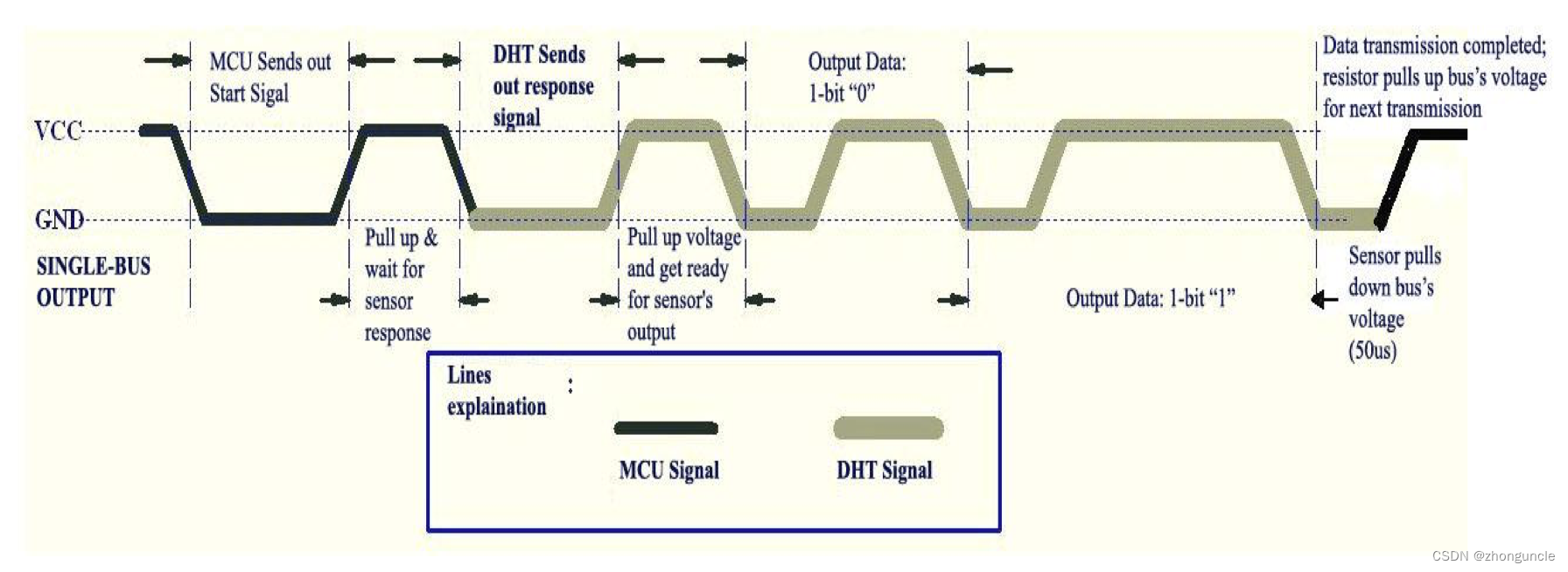
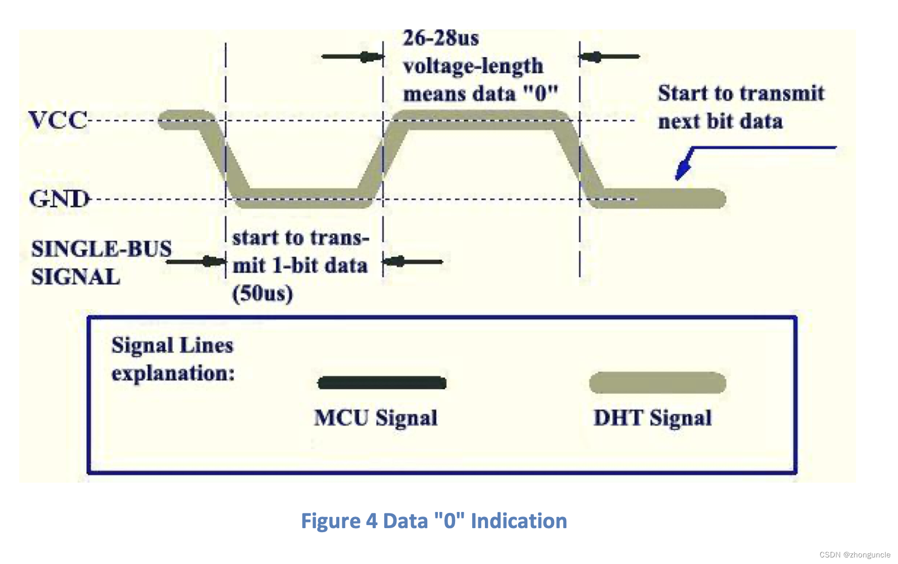
When passing data, it is judged whether it is 0 or 1 according to the following signal:
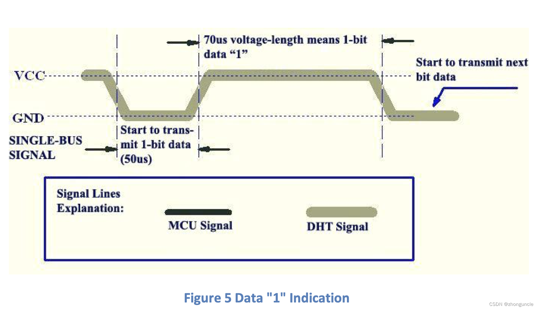
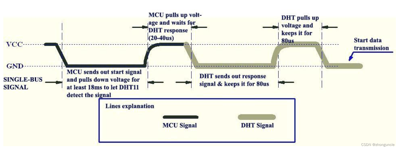
You should pay attention to the duration time here:
- At the beginning, the start signal and pulls down the voltage from Pico must no less than 18ms, so that DHT11 can obtain the signal;
- Next, Pico pulls up the voltage and waits for DHT11 to respond will takes 20~40us. This must be noted, because the relevant code in
pico-examplesdoes not wait for a response, which will be unable to obtain data, or failure to obtain data after a period of time; - DHT11 sends a response and will keep it for 80us, then pull it high and keep it for 80us;
- When transmitting data, a low level of 50us and a high level of 26~28us means that the data is a
0, and a low level of 50us and a high level of 70us means that the data is a1. - In addition, DHT11 cannot obtain data within the first 1000ms after power on. The fastest response time is 6 seconds and the slowest is 30s. Each communication takes approximately 4ms.
The 40-bit data sent by DHT11 is high-bit first, the content is: 8-bit humidity integer + 8-bit humidity floating-point number + 8-bit temperature integer + 8-bit temperature floating-point number + 8-bit checksum.
Principles and Code of DHT11
First set which GPIO pin is connected and set the maximum duration:
const uint DHT_PIN = 16;
const uint MAX_TIMINGS = 85;
Then create a structure to store the humidity and temperature obtained by DHT11:
typedef struct {
    float humidity;
    float temperature;
} dht_reading;
Next write the function to read data from DHT11
void read_from_dht(dht_reading *result) {
    // The signal value has 40 bits (5 bytes)
    int data[5] = {0, 0, 0, 0, 0};
    // Record the type of the previous signal
    uint last = 1;
    // Record the index of the current signal
    uint j = 0;

    /* Pico sending signal stage */
    // The signal direction is DHT_PIN to GPIO_OUT, sending some signals to DHT11. 'dir' is direction
    gpio_set_dir(DHT_PIN, GPIO_OUT);
    // Output low level to DHT_PIN and maintain it for 18ms, so that DHT11 can obtain this signal
    gpio_put(DHT_PIN, 0);
    sleep_ms(18);
    // Output high level to DHT_PIN and maintain it for 40us to wait for the response of DHT11
    gpio_put(DHT_PIN,1);
    sleep_us(40);

    /* DHT sending signal stage */
    // Reverse the signal direction, from DHT_PIN to GPIO_IN, to obtain DHT11 data
    gpio_set_dir(DHT_PIN, GPIO_IN);

	// Here start to obtain and process the signal from DHT11
    for (uint i = 0; i < MAX_TIMINGS; i++) {
    	//'count' to count time, unit is 255
        uint count = 0;
        // If the obtained signal level is the same as the previous signal level, it will loop. This will consume the waiting time.
        // At the beginning, DHT11 has a low level of 80us as response, so when the first loop 'last' is 1 (high level), the loop is skipped directly, and then the 'last' also becomes 0 (low level). In this way, the second cycle will enter the following loop and consume time. After DHT11 is in high level, this operation is repeated.
        //The first 50us is also processed in this way.
        while (gpio_get(DHT_PIN) == last) {
        	// Start iteration to count time
            count++;
            sleep_us(1);
            //If the current time has exceeded 100us, then the entire outer iteration will be skipped, but since break can only skip one iteration, the outer layer will have to break again.
            //Choose any value greater than the maximum period of the signal, not necessarily 100
            if (count == 100)
            	break;
        }
        //Assign the current level to DHT_PIN
        last = gpio_get(DHT_PIN);

        // This if-else is necessary, it is used to completely jump out of the outer iteration. Otherwise, the integer part of the humidity and temperature will be displayed first, and then the floating point part of the humidity and temperature will be displayed. Unable to obtain complete data in one duration
        if (count == 100)
			break;

        // Start getting data
        // i>=4 is for the first three cycles are: the response of keeping low level, pulling high level and 50us starting from the first data bit.
        // i % 2 == 0 is because the odd number of times is 50us from the beginning of the data bit, and there is no stored data.
        if ((i >= 4) && (i % 2 == 0)) {
            // j/8 indicate which byte this is
            // Shift one bit to right, so that only the rightmost bit of 8-bit needs to be set
            data[j / 8] <<= 1;
            // If the current signal time exceeds 35, then set the rightmost bit to 1
            // This 35 is because 26~28 represents 0, and any value larger than this range represents 1. Since the communication time may take some time, some redundancy is left.
            if (count > 35)
            	data[j / 8] |= 1;
            j++;
        }
    }

    // The 40-bit data obtained and the checksum (data[4] == ((data[0] + data[1] + data[2] + data[3]) & 0xFF)) is also correct, then result is saved to the structure pointed to by 'result' pointer
    if ((j >= 40) && (data[4] == ((data[0] + data[1] + data[2] + data[3]) & 0xFF))) {
        result->humidity = (float) ((data[0] << 8) + data[1]) / 10;
        if (result->humidity > 100) {
            result->humidity = data[0];
        }
        result->temperature = (float) (((data[2] & 0x7F) << 8) + data[3]) / 10;
        if (result->temperature > 125) {
            result->temperature = data[2];
        }
        if (data[2] & 0x80) {
            result->temperature = -result->temperature;
        }
    } else {
        // If data error, output debug info
        printf("Bad data\n");
    }
}
main function
Here is the main body of the entire program. The functions declared above will be used to achieve the expected effects:
int main() {
    stdio_init_all();
    /* Initial GPIO */
    gpio_init(DHT_PIN);

    /* Initial default i2c controller and pins */
    i2c_init(i2c_default, SSD1306_I2C_CLK);
    gpio_set_function(PICO_DEFAULT_I2C_SDA_PIN, GPIO_FUNC_I2C);
    gpio_set_function(PICO_DEFAULT_I2C_SCL_PIN, GPIO_FUNC_I2C);
    gpio_pull_up(PICO_DEFAULT_I2C_SDA_PIN);
    gpio_pull_up(PICO_DEFAULT_I2C_SCL_PIN);

    /* Initial SSD1306 */
    SSD1306_init();

    /* Initial rendering area of frame_area (SSD1306_WIDTH x SSD1306_NUM_PAGES) */
    struct render_area frame_area = {
        start_col: 0,
        end_col : SSD1306_WIDTH - 1,
        start_page : 0,
        end_page : SSD1306_NUM_PAGES - 1
    };

    /* calculate length of buffer for frame_area */
    calc_render_area_buflen(&frame_area);

    /* Declare a array to store buffer, the length is above */
    uint8_t buf[SSD1306_BUF_LEN];
    /* Empty the buffer and screen */
    // Assign 0 to every elements of array (because maybe memory have something, it will display blurry)
    memset(buf, 0, SSD1306_BUF_LEN);
    // Render the buffer
    render(buf, &frame_area);

    // Stores strings of temperature and humidity for rendering to the screen.
    char temp[16];
    char hum[16];

	// Wait 1000ms before the first time, otherwise the data acquisition may fail.
	sleep_ms(1000);

    /* Continuously loop to obtain data and render it to the screen */
    while (true) {
    	// Declare a variable 'dht_reading': 'reading'. And store the data read from DHT11 into 'reading'.
        dht_reading reading;
        read_from_dht(&reading);

        // Assign 0 to each element of array, otherwise the content displayed last time may still be in the buffer, which will cause problems in the next rendering and display.
        memset(buf, 0, SSD1306_BUF_LEN);

		// Generate strings for printing, store them in 'temp' and 'hum' character arrays, and then write them to the buffer array 'buf'.
        sprintf(temp, "temp = %.02f C", reading.temperature);
        // This 'printf' is for serial port USB output.
        printf("temp = %.02f C\n", reading.temperature);
        WriteString(buf, 0, 0, temp);
        sprintf(hum, "hum  = %.02f %%", reading.humidity);
        printf("hum  = %.02f %%\n", reading.humidity);
        // Since the line height is 8, the y value in the second line needs to be added to 8. If you want the line spacing to look better, you can set it to 10
        WriteString(buf, 0, 8, hum);

        // Rendering the buffer
        render(buf, &frame_area);

        // Wait 6000ms, because the minimum response time of DHT11 is 6 seconds
        sleep_ms(6000);
    }
}
CMakeLists.txt
Then enter the following content in the CMakeLists.txt file:
cmake_minimum_required(VERSION 3.12)

include(pico_sdk_import.cmake)

project(pico-temp-hum)

pico_sdk_init()

if (TARGET tinyusb_device)
	add_executable(pico-temp-hum
        	pico-temp-hum.c
        )

    # Add dependencies
    target_link_libraries(pico-temp-hum pico_stdlib hardware_adc hardware_i2c)

    # Activate USB output, turn off UART output (can open both)
    pico_enable_stdio_usb(pico-temp-hum 1)
    pico_enable_stdio_uart(pico-temp-hum 0)

    # map /bin/hex/uf2, etc.
    pico_add_extra_outputs(pico-temp-hum)

elseif(PICO_ON_DEVICE)
    message(WARNING "not building hello_usb because TinyUSB submodule is not initialized in the SDK")
endif()
Build project and burn
First go to the build directory:
$ cd build
Then build with commands:
$ cmake .. && make -j6
...
[ 98%] Building C object CMakeFiles/pico-temp-hum.dir/Users/zhongyijiang/Desktop/pico/pico-sdk/src/rp2_common/hardware_i2c/i2c.c.obj
[100%] Linking CXX executable pico-temp-hum.elf
[100%] Built target pico-temp-hum
Then burn it to the Pico.
First press and hold the “BOOTSEL” button on the Pico, then plug in the cable to connect to the computer. At this time, the Pico will enter USB storage mode.
Then drag pico-temp-hum.uf2 built into it. If you can only use the terminal, you can use the following command:
$ cp pico-temp-hum.uf2 /Volumes/RPI-RP2/pico-temp-hum.uf2
This is for macOS. If you are using Ubuntu or WSL, just change /Volumes/ to /dev/ (RPI-RP2 may need to be lowercase).
At this time, an error pop-up will be displayed. Don’t worry, it is common.
Final
At this time you can see the effect like this:
If you use a serial communication program to view it, such as minicom, use the following command:
$ minicom -D /dev/cu.usbmodem1431301 -b 115200
The cu.usbmodem1431301 here is not certain. The value may be different for each connection and needs to be modified according to the actual name.
You will see the display error in the serial communication program:
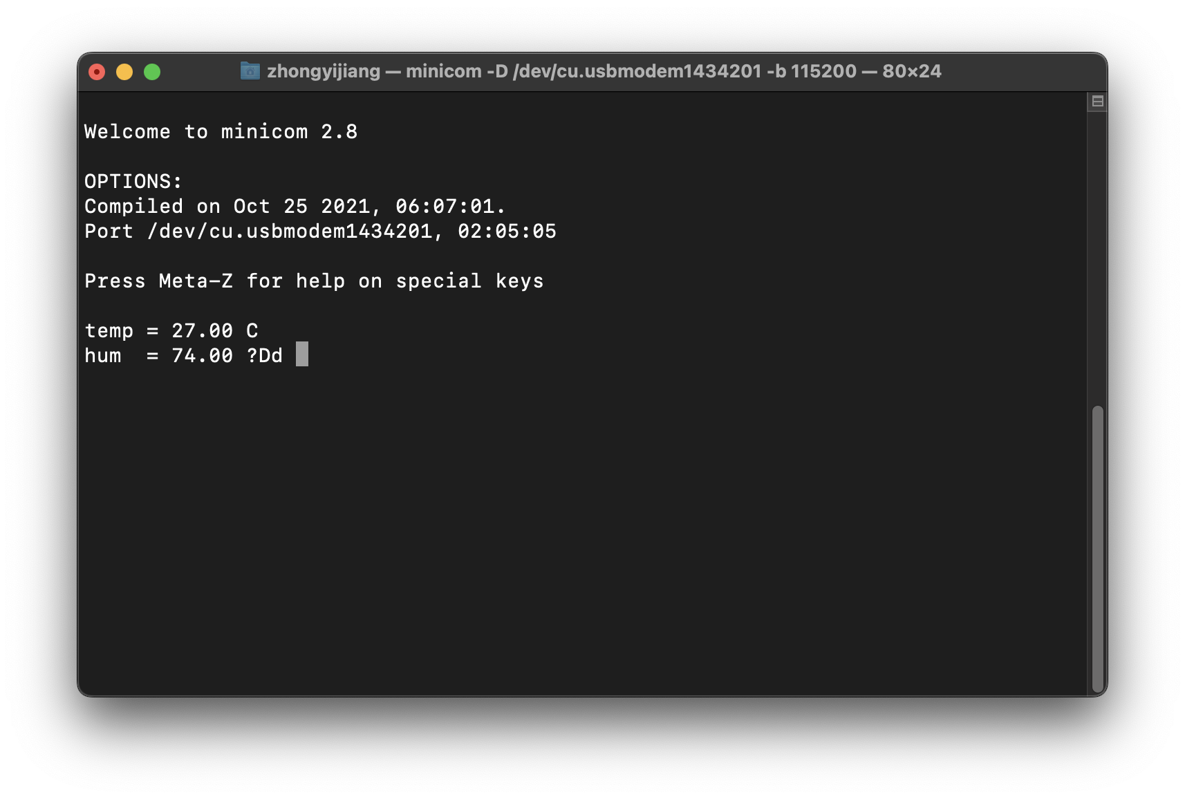
It can be seen that except for % which is not displayed well due to transmission problems, everything else is work nice and is the same as what is displayed on OLED.
I put the complete project on GitHub-ZhongUncle/pico-temp-hum-oled, and put the compiled version in the build directory The content is convenient for readers to try.
Further reading
Here are some materials that I found or referred to during the research process, as well as some blogs I wrote during the process. If you are interested, you can take a look.
SSD1306 Advance Information: This is a datasheet of SSD1306, it introduce many things, like the command.
DHT11 Humidity & Temperature Sensor: This is a document for DHT11, Some relevant information and operating mechanisms are introduced, and some images above come from this. It should be noted that the DHT11 documents of different manufacturers may be different.
https://learn.sparkfun.com/tutorials/i2c/all: This is an article introducing I2C. If you don’t know I2C, you can read it.
https://forums.raspberrypi.com/viewtopic.php?t=338243: Someone in this post asked how to modify the default I2C pin, and then the official Raspberry Pi engineer answered the method.
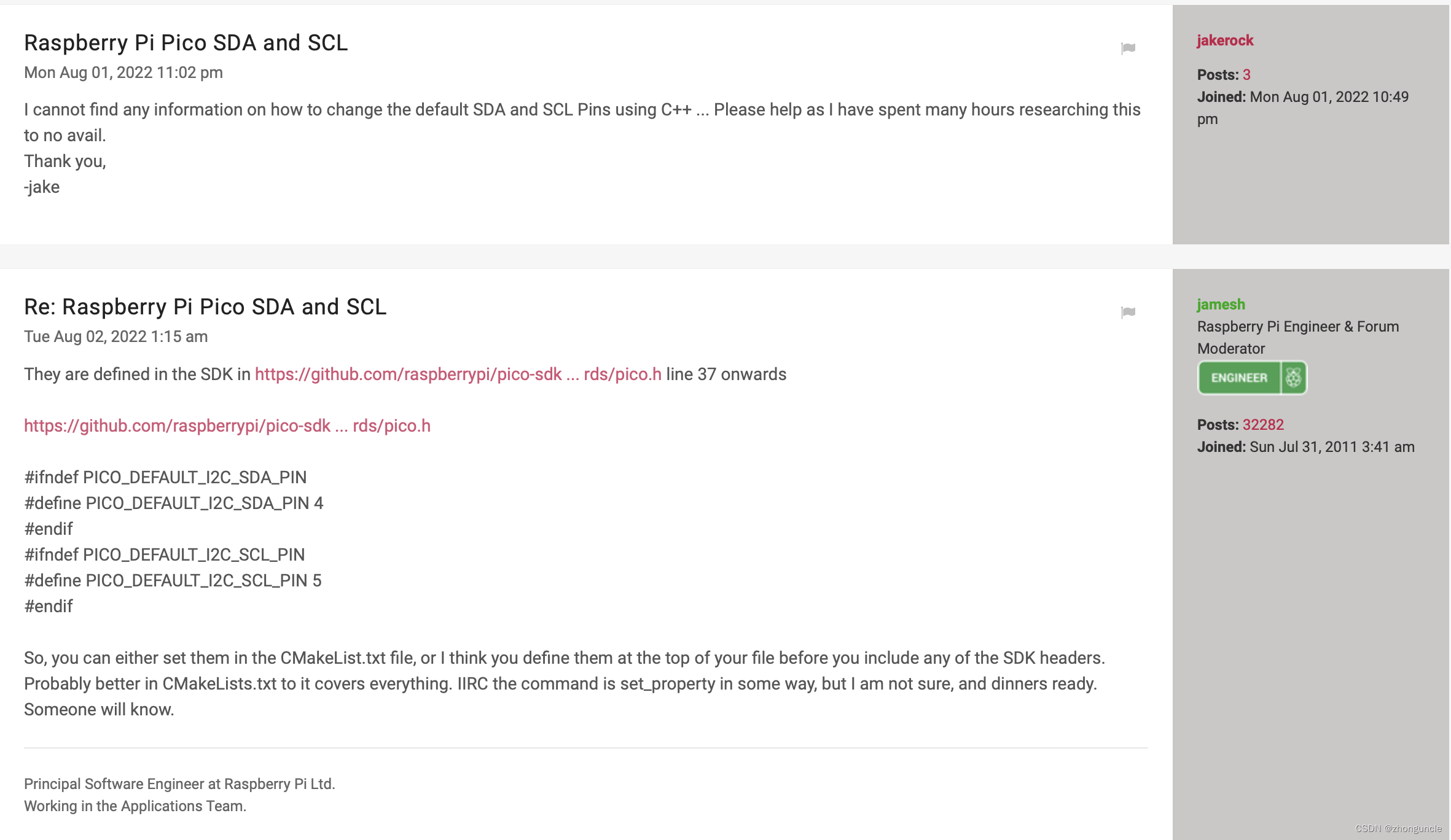
But the method defined in the source code is not quite right, as engineer said not be sure. So I wrote a blog from some trial: Modify the default SDA and SCL pins of I2C of Raspi Pico using C/C++
Then I explored how to specify a certain pin by myself, instead of using the default value or modifying the default value: Choose I2C controller, SDA and SCL pins using C/C++ on Raspberry Pi Pico
I know what the _u macro means through this post: #define _u macro?
I hope these will help someone in need~