Why Type-C in difference protocols is in difference speed
Do you wonder why Type-C in difference protocols is in difference speed? I will tell you why the Type-C have different bandwidths under different protocols from pin definitions, protocols, etc.
What is the difference between ThunderBolt 3/4 and USB Type-C
In fact, Thunderbolt 3 is an expansion set solution that includes USB 3.1 (10Gbps) and adds 40Gbps Thunderbolt 3/4 and DisplayPort 1.2, as well as PCIe, to a single Type-C interface.
In other words, Type-C is an interface type, and ThunderBolt 3/4 is a superset of USB.
Pin definition
The pin definitions of the Type-C receiver interface are as follows:
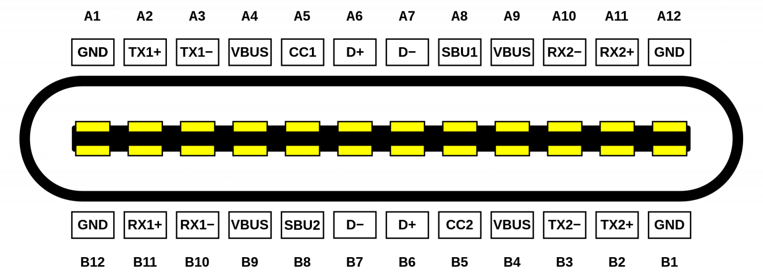
| pin | signal | pin | signal |
|---|---|---|---|
| A1 | GND | B12 | GND |
| A2 | SSTX+ | B11 | SSRX+ |
| A3 | SSTX- | B10 | SSRX- |
| A4 | VBUS | B9 | VBUS |
| A5 | CC1 | B8 | SBU2 |
| A6 | D+ | B7 | D- |
| A7 | D- | B6 | D+ |
| A8 | SBU1 | B5 | CC2 |
| A9 | VBUS | B4 | VBUS |
| A10 | SSRX- | B3 | SSTX- |
| A11 | SSRX+ | B2 | SSTX+ |
| A12 | GND | B1 | GND |
GND is the ground wire. SSTX and SSRX are differential high-speed lines for USB 3.x or TBT/DP alternate mode (Alt-Mode). There are 4 pairs in total. The “SS” here is the abbreviation of SuperSpeed, but sometimes it is ignored and called TX and RX directly. TX is the data sending end, and RX is the data receiving end. Generally, one TX will be connected to the RX end of another device, and the reverse is also true. It should be noted that the differential line transmission rate is related to many reasons, such as data processing chips, etc. VBUS supplies power to the upstream port (Power Upstream Facing Port, UFP), that is, there are 2 pairs of devices connected to the interface. CC is the abbreviation of Configuration Channel. For example, it can be used to transmit signals of the Power Delivery Protocol and implement, for example, the PD protocol. Other functions include: detecting whether the cable is inserted, detecting the direction of the cable, etc. For more information, please see: https://www.microchipdeveloper.com/usb:tc-pins D+/D- are USB 2.0 legacy signals, also used in USB 3.x, there are 2 pairs. It should be noted that if it is the caller (that is, the sender), only a6 and a7 will be used, but the receiver a6, a7, b6, and b7 will all be used, as shown below (the picture below is the male connector of a passive cable Plug into a female port on a PCB):
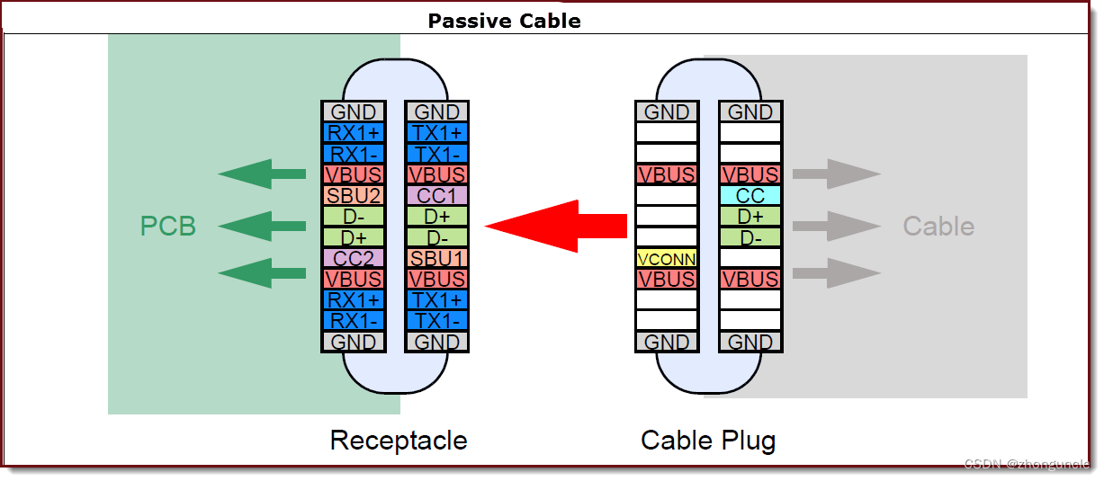
SBU is the abbreviation of Sideband Use. USB does not use these two interfaces and is only used in alternate modes (Alt-modes). When the SBU is in DP Alt mode, it will serve as the AUX_P/AUX_N differential line in the DP protocol (its polarity can be modified according to the forward and reverse insertion directions), responsible for transmitting key information such as DPCD and EDID of the device.
Looking at the picture above, we can see that the pin of CC2 is at the transmitting end VCONN and is used for electronic marking cable power supply (Plug power). Both CC1 and CC2 need to support CC (Configuration Channel) and VCONN.
In a technical sense, Type-C is divided into two fronts. Although the user does not distinguish between front and back when inserting, the interface itself is actually divided. For more details, check: https://www.microchipdeveloper.com/usb:type-c
Taking the NS power adapter as an example, the NS power adapter supports 5V1.5A (7.5W) or 15V2.6A (39W) output. The following figure is the Type-C connector wiring diagram:
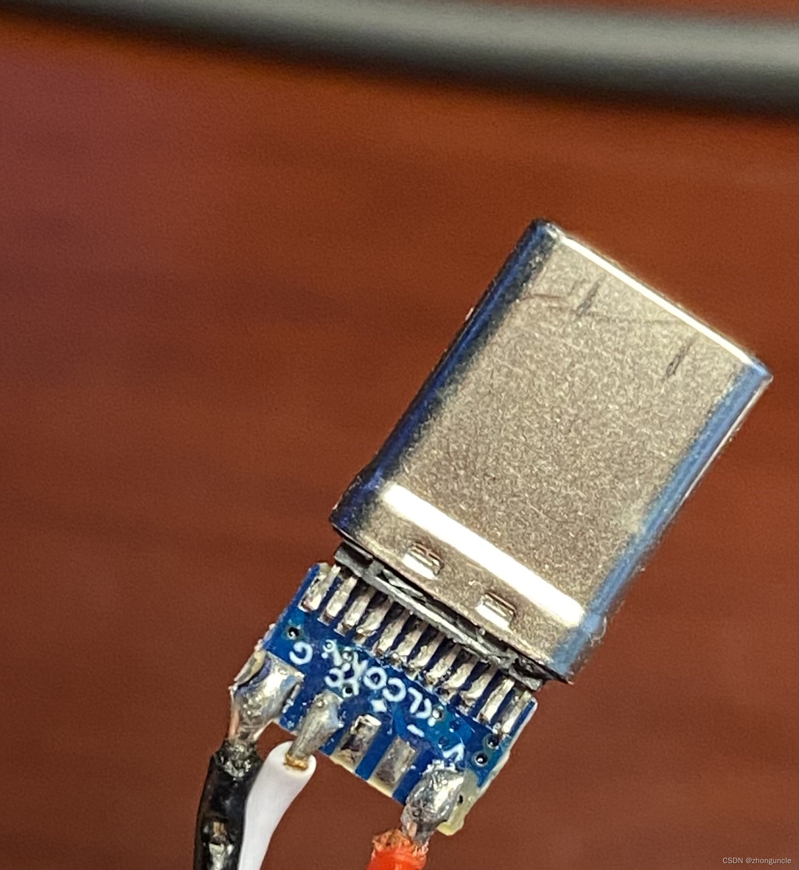
You can see that G (ground wire), cc (used to implement the charging protocol) and V (current transmission) are connected, and then these three solder joints are connected to the Type-C pins through the copper wires on the PCB.
USB data stream
The full name of USB 3.0 is Super Speed USB, which supports up to 5 Gbps. (USB 3.0 is now also called USB 3.1 Gen 1) The full name of USB 3.1 is SuperSpeed Plus USB, which supports up to 10 Gbps. (USB 3.1 is now also called USB 3.1 Gen 2) The data signals for both are the same:
- D+ and D- differential half-duplex signaling
- Two pairs of full-duplex differential signals (SSTX-, SSTX+ and SSRX-, SSRX+)
In addition to the higher speeds supported by USB 3.1 controllers, another difference is the encoding in full-duplex mode: USB 3.0 is 8b/10b; USB 3.1 is 128b/132b. To put it simply: 8b/10b means mapping 8-bit data to 10-bit, supporting balanced transmission of 0s and 0s in the encoded stream, and can also detect transmission errors, consuming 20% of the bandwidth. 128b/132b means the same thing, but the loss is reduced to about 3%. For the implementation and high-speed transmission of 8b/10b, you can read this paper: “8B/10B Encoding and Decoding for High Speed Applications”
For more information and comparison about USB, please read this article: Understanding the USB 3.1 protocol
Here is a PPT with a good related demonstration and summary: “TypeC (USB3.1/3.0) Introduction and Test solution”
DisplayPort data stream
DisplayPort Alt Mode for USB-C (other modes are described in the ThunderBolt section) will occupy 1, 2, or all 4 pairs of high-speed differential lines. Then a new concept will be mentioned: HBR (DisplayPort High Bit Rate). HBR determines the bandwidth of each high-speed differential line occupied by DP.
- The bandwidth of HBR is 2.70 Gbps.
- The bandwidth of HBR 2 is 5.40 Gbps.
- The bandwidth of HBR 3 is 8.10 Gbps.
- The bandwidth of UHBR 10 is 10.00 Gbps.
- The bandwidth of UHBR 13.5 is 13.50 Gbps.
- The bandwidth of UHBR 20 is 20.00 Gbps.
For example, DP 1.2 supports the highest HBR 2, so the maximum bandwidth is 21.6 Gbps (5.40 Gbps x4), using 8b/10b encoding, and the maximum data rate of four channels is 17.28 Gbps. The bandwidth required by 4k 60hz 10bit per second is about 14.93 Gbps, which is almost full. So DP 1.2 supports up to 4k60hz.
HBR version depends on the output device. For example, Intel’s core display only supports HBR 3 starting from Tiger Lake. This is why new core display CPUs such as 12600K support a maximum DP output of 7680x4320@60hz, while HDMI is still 4096x2160@60hz.
This document from Dell explains the devices that Dell supports HBR 3: https://www.dell.com/support/kbdoc/zh-cn/000183937/dell-systems-support-hbr3-specifications
Here is a good introduction and table of DP, which explains it very clearly: “DisplayPort Interface- What is DP?”
Full-featured Type-C
When connecting a notebook and a 4K monitor with a Type-C cable, you may encounter the choice of using up to 4K 60hz and USB 2.0, or using up to 4K 30hz and USB 3.1 (10 Gbps). Why is this?
As mentioned earlier, USB 3.x only uses 2 pairs of high-speed differential lines and D+ and D- differential half-duplex lines, which can reach a rate of 10 Gbp. This leaves only 2 pairs of high-speed differential lines. DisplayPort Alt Mode can occupy 1/2/4 pairs of high-speed differential lines, so it only occupies 2 high-speed differential lines (because generally only the TX pin is occupied to send display signals and data, so it is 2 instead of 2 For 4), 2 high-speed differential lines can achieve 10.4 Gbps bandwidth at HBR 2. However, this cannot meet the bandwidth required per second for 4k 60hz 10bit (approximately 14.93 Gbps), so it can only achieve 4k 30hz 10bit (approximately 7.47 Gbps). This is why USB Type-C single cable can only do 4k 30hz 10bit and USB 3.1 Gen2 (10 Gbps).
If you want to achieve 4k 60hz 10bit, you have to occupy all 4 high-speed differential lines. Then USB can only use the two differential half-duplex lines D+ and D-, and this can only achieve USB 2.0.
So if you want 4k 60hz 10bit, then USB can only have USB 2.0.
ThunderBolt 3/4
The first thing to know is that ThunderBolt is a two-way dual protocol (PCIe and DisplayPort). A ThunderBolt controller will connect 4 PCIe lanes (minimum 2), and the number of DP corresponding to the number of ports (for example, two ThunderBolt interfaces, then from the video output device, such as CPU core display or indirectly through PCH, there will be two The DP line is connected to the ThunderBolt controller, one DP line occupies 4 high-speed differential lines).
Apple has a good document to introduce the operating principle of ThunderBolt controller, you can check it out: “Thunderbolt Technology Overview” There are also two official PPTs to introduce ThunderBolt 3, including the operating principle of ThunderBolt 3 controller: “ThunderBolt Update” and “ThunderboltTM” 3 Technology and USB-C》
ThunderBolt 3/4 will use all 4 pairs of high-speed differential lines. However, the signal distribution is different in different modes.
- ThunderBolt Alt Mode: Using ThunderBolt-enabled cables and devices, the ThunderBolt controller will distribute 2 pairs of high-speed differential lines in each direction to create two complete duplex bidirectional 40 Gbps channel (there are also two ThunderBolt 3 ports sharing a ThunderBolt controller, or the bandwidth is limited, so the bandwidth of one interface is only 20 Gbps).
- USB Only Mode: For USB devices or cables that do not support ThunderBolt, the ThunderBolt port activates the USB controller to support USB 3.x or 2.0 signals.
- DisplayPort Alt Mode: When a DisplayPort monitor or adapter is plugged into a ThunderBolt connector, the controller activates DisplayPort Alt Mode. In this mode, 4 pairs of high-speed differential lines will be pointed in the same direction (that is, 8 lines are output at the same time) to support high-resolution output (ThunderBolt 4 supports DisplayPort 2.0, which is the highest UHBR 20, the highest bandwidth It can reach 80 Gbps (not counting coding loss), and can support three 10k or one 16k monitor; ThunderBolt 3 supports DP 1.2, which is the highest HBR 2, and the highest bandwidth is 43.2 Gbps (not counting coding loss), which can support 2 sets of 4k 60hz 10bit, 1 set of 4k 120hz or 1 set of 5k 60hz monitors).
- USB/DP Combo Mode: In this mode, the controller automatically adjusts the channels occupied by USB and DisplayPort, which together occupy 4 pairs of high-speed differential lines. Because of this, monitors that support Thunderbolt interface can achieve 4K or even 5K 60hz, and also support at least one USB 3.1 and Gigabit network port.
Differences between ThunderBolt 3 and 4
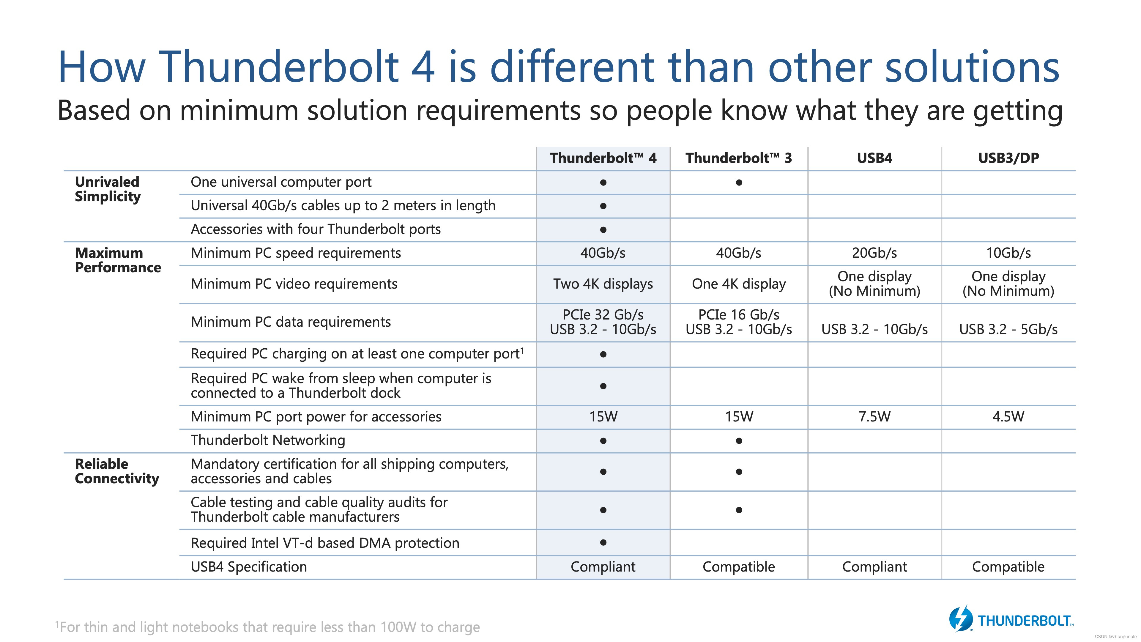
If you look it up, you will find that ThunderBolt 4 has two major updates compared to ThunderBolt 3:
-Support DisplayPort 2.0 (that is to say, support UHDR 20, so that the DP bandwidth can reach up to 80 Gbps, and because the encoding is changed to 128b/132b, the loss is also lower)
- Minimum PCIe data requirement increased from 16 Gbps to 32 Gbps.
The former is easy to understand, the latter needs an explanation. First, you need to know the relationship between ThunderBolt controller and PCIe.
A ThunderBolt controller must be connected to at least 2 PCIe lanes and up to 4 lanes. For best performance, 4 is definitely better, but why do we need two? My personal guess is that this is because the CPU PCIe lanes on some devices are not enough, so each ThunderBolt controller cannot be forced to connect to 4 PCIe lanes to correspond to each high-speed differential line one by one. For example, the 9900K only has 16 PCIe 3.0 lanes and is connected to the chipset (Platform Controller Hub, PCH) through DMI 3.0. The DMI 3.0 bandwidth is only 8 GT/s, which is equivalent to 4 PCIe 3.0 lanes (32 Gbps). PCH extends to 24 more PCIe lines. These 16 PCIe 3.0 strips of the CPU are rarely used to connect ThunderBolt controllers. Because independent graphics cards, NVMe hard drives, and redundant expansion PCIe slots will occupy this part. Looking at the PCH part, the DMI 3.0 bandwidth is only 32 Gbps, and it must share the bandwidth with sound cards, network cards, wireless network cards, hard disks and other devices. Therefore, although the ThunderBolt controller connected to the PCH through 4 PCIe can theoretically reach a bandwidth of 32 Gbps, it is very likely to be limited by the bandwidth of DMI 3.0, and may even be lower than the 16 Gbps brought by 2 PCIe. bandwidth. And because there is one more step to pass, the delay will be much higher. So only on Macs and very few PCs, ThunderBolt controllers connect directly to the CPU. Then the bandwidth of this part of the equipment is relatively stable, relatively high, and the latency is low.
Then the minimum total PCIe bandwidth of ThunderBolt 3 is 2 x 8 Gbps, which is 16 Gbps. This is half-speed ThunderBolt 3, and the bandwidth is generally marked as 20 Gbps. The bandwidth of 4 PCIe 3.0 connections is 32 Gbps, which is full-speed ThunderBolt 3. The bandwidth is generally marked as 40 Gbps.
Here is an explanation of the meaning of ThunderBolt’s 20 Gbps and 40 Gbps. This meaning does not mean that the bandwidth of PCIe is 20/40Gbps. It is the lowest bandwidth for transmitting any type of data, including video signals and data transmission. For example, in DP HBR2 mode, the total bandwidth of four channels is 21.6 Gbps, and the two displays are 43.2 Gbps. Dell said that the actual PCIe bandwidth or data transmission bandwidth is only 7-22 Gbps, and it is officially limited). I also saw the same comment on the forum, but the reason was explained - because some controllers support two output interfaces, 10 Gbps is reserved for USB 3.1 Gen 2.
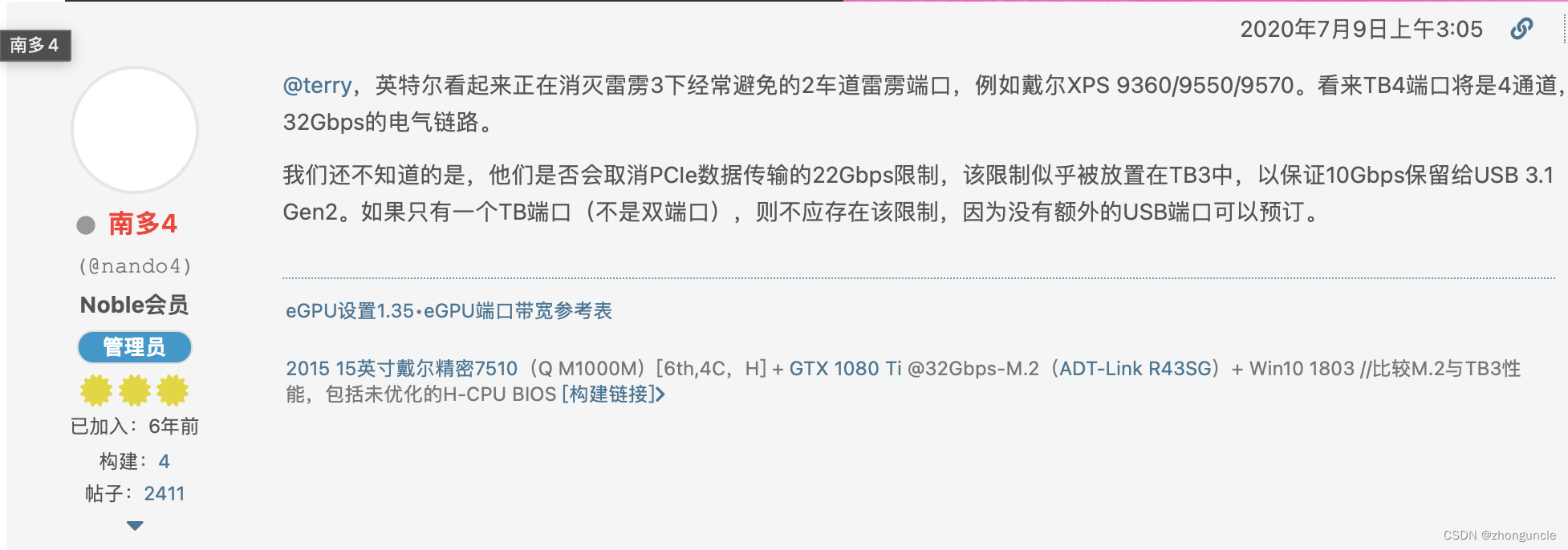
In other words, even if ThunderBolt 3 is given 4 PCIe lanes and is directly connected to the CPU, it can only reach about 22 Gbps. The improvement in ThunderBolt 4 is mainly due to the mandatory limit of the minimum PCIe bandwidth to 32 Gbps, which is a big improvement for many external PCIe devices (and may remove the 10 Gbps reservation).
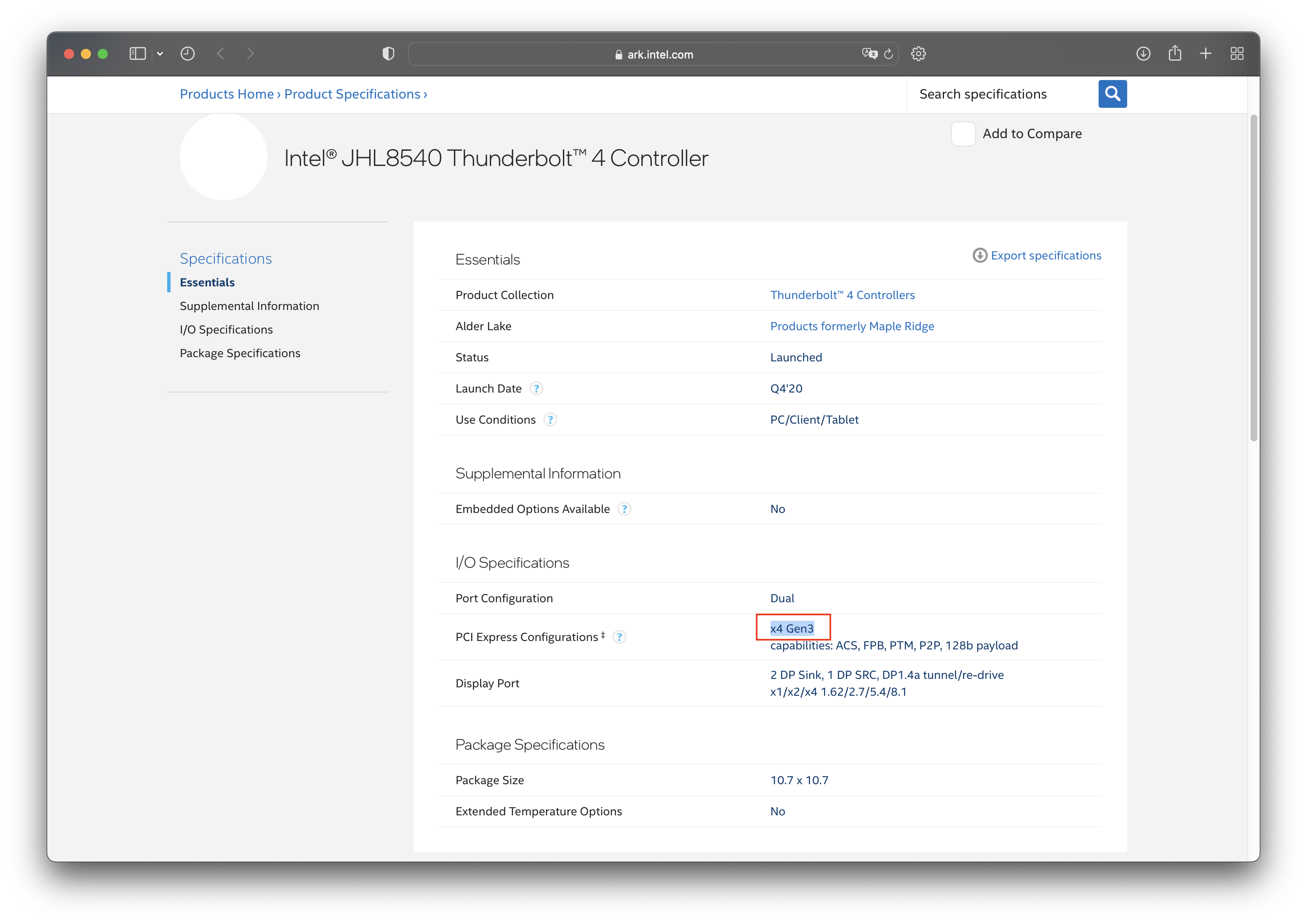
It should be noted that this improvement is only mandatory and not due to PCIe upgrade. Because Intel has put the ThunderBolt 3/4 controller directly into the CPU since Tiger Lake, without occupying any allocable PCIe lanes. In this way, Tiger Lake’s ThunderBolt 3 can fully use the bandwidth of 4 PCIe 3.0, and can also reach 32 Gbps. And if you check the external controller of ThunderBolt 4, such as Intel® JHL8540 Thunderbolt™ 4 Controller, you will find that it is PCIe 3.0 x4, as shown in the following figure:
Oh, there is also a post here, which introduces the loss of some graphics cards connected through ThunderBolt: eGPU Performance Loss - PCI Express vs. Thunderbolt
I hope these will help someone in need~